Industry news
By: Jetvision
Aug 14,2026
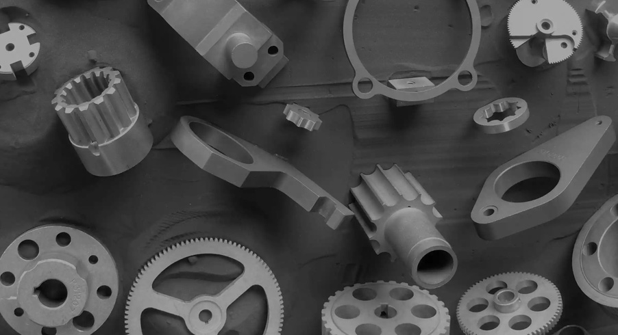
Metal Injection Molding (MIM) is an efficient manufacturing process for producing small, complex metal components in medium to high production volumes. By combining fine metal powders with injection molding technology, MIM can produce geometries that are difficult or expensive to manufacture through conventional machining or pressing.
However, not every part is automatically suitable for MIM. Good part design is essential for controlling tooling costs, dimensional variation, sintering deformation, and overall production cost.
This MIM design guide explains the key factors engineers and OEM buyers should consider when designing metal injection molded parts.
What Makes a Good MIM Part?
MIM is particularly suitable for components that are:
· Small and relatively lightweight
· Geometrically complex
· Required in medium or high production volumes
· Difficult or expensive to machine
· Made from materials suitable for MIM
· Required to maintain consistent dimensions across large production runs
Typical applications include MIM lock components, mechanical parts, hardware components, gears, consumer electronics components, and precision industrial parts.
The biggest advantage of MIM is its ability to combine multiple features into one molded component, reducing the need for multiple machining operations and assembly.
1. Keep Wall Thickness as Uniform as Possible
Wall thickness is one of the most important design considerations in MIM.
Large variations in wall thickness can cause differences in material flow, debinding behavior, and sintering shrinkage. These differences may result in distortion or dimensional variation.
Where possible, designers should maintain relatively uniform wall thickness throughout the part.
If a thick section is required, consider using:
· Ribs · Hollow sections · Core features · Redesigned transitions
instead of simply increasing the solid wall thickness.
Uniform geometry generally provides better process stability and dimensional consistency.
2. Use Appropriate Draft Angles
Although MIM uses metal feedstock rather than plastic, the component is still injection molded and must be removed from the mold.
Appropriate draft angles can make mold release easier and reduce the risk of damage to the molded part.
The required draft depends on factors such as:
· Part geometry · Surface finish · Mold design · Material · Depth of the feature
Early communication between the part designer and MIM supplier can help determine an appropriate draft angle before tooling begins.
3. Design Holes and Cores Carefully
MIM can produce a wide range of holes and internal features.
However, the geometry and orientation of a hole strongly influence tooling complexity.
Straight-through holes aligned with the mold opening direction are generally easier to produce.
More complicated features may require:
· Side cores · Slides · Inserts · Additional tooling mechanisms
These features can increase mold complexity and tooling cost.
Therefore, when designing a MIM component, engineers should consider the direction of mold opening at the beginning of the design process.
4. Avoid Unnecessary Undercuts
Undercuts can often be produced with MIM, but they usually require additional mold mechanisms.
For example, a side undercut may require a slide or lifter. While such features are technically possible, they can increase tooling cost and maintenance requirements.
If an undercut is not functionally necessary, eliminating or redesigning it may reduce the overall cost of the component.
For complex parts, however, the ability of MIM to incorporate undercuts can still be a major advantage over conventional powder compaction.
5. Consider Parting Lines Early
Every injection mold has a parting line where the mold sections meet.
The location of this line can affect:
· Appearance · Dimensional accuracy · Flash · Tooling complexity · Secondary finishing requirements
For visible or functional surfaces, designers should discuss the preferred parting line location with the MIM supplier before mold design.
A well-planned parting line can reduce unnecessary finishing operations.
6. Think About Gate and Ejector Locations
The position of the injection gate affects how the feedstock flows into the mold cavity.
For simple components, gate placement may be relatively straightforward. Complex MIM components may require careful flow analysis to avoid:
· Weld lines · Air traps · Incomplete filling · Uneven material distribution
Ejector pins are also necessary to remove the molded part from the mold.
Whenever possible, ejector marks should be positioned on non-critical surfaces.
7. Be Realistic About Tolerances
MIM can achieve excellent dimensional consistency, but not every dimension should automatically be assigned an extremely tight tolerance.
Tight tolerances increase manufacturing difficulty and may require secondary machining or additional inspection.
A better approach is to identify:
Which dimensions are functionally critical?
and
Which dimensions can use a more relaxed tolerance?
For example, a mating diameter may require tighter control than a non-functional exterior surface.
Designing only critical dimensions with tighter tolerances can significantly improve cost efficiency.
8. Account for Sintering Shrinkage
One important difference between MIM and conventional machining is that MIM parts undergo significant dimensional change during debinding and sintering.
The molded "green" component is intentionally oversized, and the final component shrinks during sintering.
The exact shrinkage depends on factors such as:
· Material · Feedstock · Part geometry · Processing conditions · Furnace atmosphere · Orientation
MIM tooling therefore needs to be designed around the expected final dimensions rather than simply copying the nominal dimensions of the finished part.
9. Combine Multiple Features Into One Component
One of the strongest advantages of MIM is the ability to integrate multiple features into one component.
A part that requires several CNC machining operations may potentially be molded as one MIM component.
For example, a small lock component may contain:
· Holes · Slots · Steps · Curved surfaces · Bosses · Functional interfaces
Instead of machining each feature separately, MIM can potentially form many of these features during molding.
This can reduce: · Machining time · Material waste · Assembly operations · Number of individual components
10. Design for the Complete Manufacturing Process
The best MIM design is not simply the easiest shape to mold.
It should be optimized for the entire process:
Feedstock → Injection Molding → Debinding → Sintering → Secondary Operations → Inspection
A design that looks simple during molding may create problems during debinding or sintering.
For this reason, it is beneficial to involve the MIM supplier early in the product development process.
Good MIM design balances function, geometry, tooling, dimensional requirements, production volume, and cost.
MIM is particularly powerful when a component is small, complex, and required in significant quantities. With proper design, many features that would otherwise require multiple machining operations can be produced directly during molding.
If you have a 2D drawing or 3D model, an experienced MIM supplier can review the geometry and identify opportunities to simplify tooling, improve manufacturability, and reduce production cost.
Back to Top