Industry news
By: Jetvision
Nov 20,2026
Metal Injection Molding (MIM) enables the production of complex, near-net-shape metal components for medical devices, automotive systems, consumer electronics and industrial applications. However, maintaining consistent dimensional accuracy remains one of the key challenges in MIM manufacturing.
During sintering, MIM components typically undergo approximately 15–20% linear shrinkage, depending on the feedstock formulation, material system and processing conditions. This significant dimensional change must be accurately predicted and controlled to ensure that finished parts meet drawing specifications and assembly requirements.
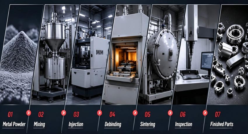
Dimensional accuracy in MIM cannot be achieved through a single manufacturing step. It requires coordinated control across the entire production process, including feedstock preparation, mold design, injection molding, debinding, sintering, secondary machining and final inspection. Variations introduced at any stage can affect the final dimensions and consistency of finished components.
For precision MIM manufacturers, the key is to establish a systematic dimensional control process from initial material preparation through mass production.
Feedstock and Powder Consistency: The Foundation of Predictable Shrinkage
Dimensional stability begins with consistent feedstock quality. MIM feedstock consists of fine metal powder combined with a multi-component binder system. The uniformity of this mixture directly influences mold filling, green part density and subsequent sintering behavior.
Manufacturers carefully control powder characteristics, including particle size distribution, particle morphology, chemical composition and oxygen content. Variations in powder properties can affect packing density and sintering behavior, potentially resulting in inconsistent shrinkage or dimensional distortion.
Binder formulation and powder loading are equally important. The powder-to-binder ratio, mixing uniformity and feedstock flow characteristics must remain stable between production batches. Poorly mixed feedstock or inconsistent flow behavior can cause powder-binder separation during injection, creating density variations within molded parts.
To minimize these risks, manufacturers monitor feedstock rheological properties, mixing parameters and material consistency before production. Stable feedstock provides the foundation for predictable shrinkage and repeatable dimensional results.
Mold Design and Shrinkage Compensation: Predicting Final Dimensions
Unlike conventional machining, MIM mold cavities must account for the dimensional shrinkage that occurs during sintering. Therefore, mold dimensions are designed larger than the required final part dimensions.
However, shrinkage compensation is not a universal value. It depends on several factors, including:
· Metal powder composition and particle characteristics
· Powder loading and binder formulation
· Part geometry and wall thickness distribution
· Injection molding conditions
· Debinding and sintering parameters
Before mold manufacturing, engineers evaluate part geometry and identify critical-to-quality dimensions, such as bore diameters, mounting holes, gear profiles, sealing surfaces and assembly interfaces.
Mold filling simulation and previous process data can help optimize gate locations, runner design and filling balance. For complex components, these evaluations help reduce potential density differences and minimize distortion during subsequent processing.
For high-precision projects, mold development usually involves trial molding, dimensional measurement and iterative cavity adjustments. Actual shrinkage data from initial production trials is used to refine mold dimensions and improve the consistency of finished components.
Injection Molding: Establishing Consistent Green Part Quality
Injection molding plays a critical role in determining the dimensional consistency of MIM components. At this stage, metal powder feedstock is injected into the mold to form green parts. Variations in filling behavior, packing density and residual stress can affect subsequent shrinkage and final dimensions.
Key process parameters include:
· Feedstock temperature
· Mold temperature
· Injection speed and pressure
· Holding pressure and time
· Injection cycle consistency
These parameters must be optimized according to the material formulation and component geometry. Inadequate filling or packing may result in internal voids and density variations, while excessive or uneven packing can introduce residual stress that contributes to distortion during debinding and sintering.
For complex components with thin walls, small holes or uneven cross-sections, mold filling behavior requires particular attention.
Manufacturers use controlled injection parameters and repeatable production cycles to maintain consistent green part quality. Proper handling and transfer procedures are also necessary because green parts are relatively fragile and can be damaged or deformed before debinding.
Debinding Control: Preventing Cracks and Dimensional Distortion
Debinding removes the binder from molded green parts, leaving a porous metal structure known as the brown part. Although the main dimensional shrinkage occurs during sintering, improper debinding can introduce defects that affect final dimensional accuracy.
If binder removal is too rapid or uneven, internal gas pressure and localized stress may cause cracking, blistering or deformation. These defects can become more pronounced during subsequent sintering.
Depending on the feedstock system and material requirements, manufacturers may use solvent, catalytic or thermal debinding processes, or a combination of different methods.
Heating rates, processing time, atmosphere and debinding conditions must be carefully controlled to ensure uniform binder removal. Part geometry also influences the selection of the debinding process, particularly for components with thick sections, thin walls or complex internal features.
Consistent debinding helps preserve part integrity and prepares the brown parts for controlled densification during sintering.
Sintering: Controlling Temperature, Atmosphere and Part Support
Sintering is one of the most critical stages in MIM dimensional control. During this process, metal particles bond together and densify under controlled thermal conditions. Most of the characteristic dimensional shrinkage occurs at this stage.
Three factors have a significant influence on dimensional consistency: temperature uniformity, furnace atmosphere and part support.
Temperature control
Sintering temperature, holding time and heating or cooling rates must be matched to the material system. Uneven temperature distribution within the furnace can cause differences in densification and shrinkage between components in the same batch.
Manufacturers monitor furnace temperature uniformity and maintain stable thermal conditions according to the established process specifications.
Atmosphere control
Depending on the material, sintering may be performed in vacuum or controlled atmospheres such as hydrogen- or nitrogen-based environments. Proper atmosphere management helps prevent oxidation and control chemical changes that could affect material properties and sintering behavior.
Part support and loading orientation
Component geometry is another important consideration. Long, thin, flat or asymmetrical structures may be more susceptible to sagging, warping or distortion during high-temperature processing.
To reduce these risks, manufacturers may use suitable ceramic setters, support fixtures and controlled loading orientations. Consistent furnace loading arrangements help ensure that parts experience repeatable thermal conditions from batch to batch.
Secondary Sizing and Post-Processing for Tighter Tolerances
As-sintered MIM components can achieve relatively good dimensional accuracy, but the achievable tolerances depend on material, geometry, component size and manufacturing conditions.
When drawing requirements are tighter than the established as-sintered capability, targeted secondary operations may be necessary.
Common finishing methods include:
· Sizing and coining
· Reaming and precision drilling
· CNC machining
· Grinding
· Honing and lapping
These operations are generally applied to critical dimensions rather than the entire component. For example, precision machining may be required for bearing interfaces, mounting holes, sealing surfaces and mating features.
This approach helps balance dimensional requirements with manufacturing costs while preserving the economic advantages of the MIM process.
During the design and quotation stage, experienced MIM manufacturers evaluate which dimensions can be achieved directly through molding and sintering and which require additional machining allowances. Early communication between the customer and manufacturer helps avoid unnecessary tooling changes and production costs.
Dimensional Inspection, SPC and First Article Validation
Effective dimensional control requires reliable measurement methods and continuous process monitoring. Manufacturers use different inspection instruments according to component geometry, tolerance requirements and production volume.
Common measurement equipment includes:
· Digital micrometers and calipers
· Optical comparators
· Vision measurement systems
· Coordinate Measuring Machines (CMM)
· Dedicated gauges and inspection fixtures
For mass production, Statistical Process Control (SPC) helps monitor critical dimensions and identify process variations before they lead to widespread nonconforming products.
Typical critical-to-quality dimensions include bore diameters, hole positions, wall thicknesses, overall dimensions and assembly interfaces. Process capability indices such as Cp and Cpk can be used to evaluate whether the manufacturing process consistently meets specified tolerances.
When dimensional trends move outside established control limits or capability targets, manufacturers investigate potential causes, including feedstock variations, mold wear, injection parameter changes and furnace process fluctuations.
For new projects, First Article Inspection (FAI) verifies whether the initial components meet drawing requirements before proceeding to mass production. Inspection results, process parameters and dimensional data can then be used to establish production controls for subsequent batches.
Consistent Dimensional Accuracy Requires Full-Process Control
Maintaining dimensional accuracy in Metal Injection Molding is a systematic manufacturing task rather than the result of a single adjustment. Predictable shrinkage, stable feedstock, accurate mold compensation, consistent injection molding, controlled debinding and sintering, and reliable inspection all contribute to the final dimensional performance of MIM components.
For buyers sourcing precision MIM parts, evaluating a supplier's dimensional control capabilities is just as important as comparing material specifications and manufacturing prices.
A capable MIM manufacturer should be able to assess component geometry, identify critical dimensions, establish appropriate shrinkage compensation and determine whether secondary machining is required to meet drawing specifications.
At Jetvision, we support custom MIM component projects through manufacturing process evaluation, tooling development, production control and dimensional inspection. If you have a custom metal injection molding project with specific tolerance requirements, send us your drawings for a technical review and quotation.
Back to Top