Industry news
By: Jetvision
Oct 08,2026
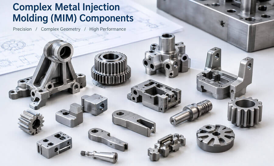
Metal Injection Molding (MIM) is an effective manufacturing process for producing small, complex metal components with intricate geometries, fine details, and consistent quality. By combining metal powders with a binder system, MIM enables the production of near-net-shape parts that would be difficult or costly to manufacture through conventional machining.
However, successful MIM manufacturing starts with proper part design. Wall thickness, feature geometry, dimensional tolerances, material selection, and sintering behavior all influence component quality, production efficiency, and manufacturing cost.
For engineers and product developers considering custom MIM parts, understanding these design considerations early can help reduce tooling modifications, minimize defects, and improve the feasibility of mass production.
Optimize Wall Thickness and Uniformity
Wall thickness is one of the most important considerations in MIM part design. Although metal injection molding can accommodate complex geometries, significant variations in wall thickness may cause uneven binder removal, differential shrinkage, and dimensional distortion during debinding and sintering.
Whenever possible, designers should aim for relatively uniform wall sections and avoid abrupt transitions between thick and thin areas.
For sections where thickness changes are unavoidable, gradual transitions and rounded connections can help improve material flow and reduce stress concentrations. Ribs, bosses, and reinforcing features should also be designed with consideration for their influence on local thickness and sintering behavior.
The appropriate wall thickness depends on the component's overall dimensions, material, geometry, and performance requirements. Rather than applying a universal minimum thickness, it is advisable to review critical sections with the MIM manufacturer during the design stage.
Design Complex Geometries for Moldability
One of the main advantages of metal injection molding is its ability to produce complex metal components with features such as undercuts, grooves, slots, ribs, and integrated functional details.
These features can reduce the need for secondary machining and assembly. However, geometric complexity should serve a functional purpose rather than increase tooling complexity unnecessarily.
During MIM design optimization, engineers should evaluate:
· Undercuts and side features: Determine whether slides, lifters, or other specialized tooling mechanisms are required.
· Deep and narrow cavities: Assess mold filling, tool accessibility, and the feasibility of ejecting the molded component.
· Thin ribs and small protrusions: Consider filling behavior, tooling durability, and the risk of damage during ejection.
· Sharp corners and edges: Use suitable radii where possible to improve material flow and reduce stress concentrations.
· Integrated features: Combine multiple functions into one component when this can simplify assembly without compromising performance.
A design review before mold fabrication helps identify features that may increase tooling cost or introduce manufacturing risks.
Consider Dimensional Tolerances and Sintering Shrinkage
Dimensional accuracy is a critical factor when designing precision MIM components. During manufacturing, the feedstock is injected into a mold, the binder is removed, and the metal powder is sintered to form a dense metal part. Significant dimensional shrinkage occurs during sintering.
MIM tooling must account for this shrinkage, which varies depending on the material system, component geometry, process conditions, and production controls.
Designers should distinguish between critical dimensions and non-critical dimensions rather than applying unnecessarily tight tolerances to every feature.
For example, dimensions affecting assembly interfaces, bearing locations, mating surfaces, and functional clearances may require tighter control. Other dimensions may be suitable for standard process tolerances.
For components requiring higher precision, the design may incorporate machining allowances on selected surfaces. Post-sintering machining, grinding, or other finishing operations can then be used where necessary.
The achievable tolerance should be confirmed with the manufacturer based on the actual component geometry, material, size, and inspection requirements.
Select the Right Material for the Application
Material selection affects the mechanical properties, corrosion resistance, wear resistance, magnetic characteristics, and long-term performance of MIM components.
Common MIM material options include stainless steels, low-alloy steels, tool steels, and selected soft magnetic alloys. The appropriate grade depends on the component's service environment and functional requirements.
For example:
· Stainless steel MIM parts: Suitable for applications requiring corrosion resistance, including selected medical devices, consumer products, electronic hardware, and industrial components.
· Low-alloy steel MIM parts: Considered for components requiring suitable strength and mechanical performance.
· Tool steel MIM parts: Used for selected wear-resistant components and precision tooling-related applications.
· Soft magnetic alloy MIM parts: Suitable for specific electromagnetic applications where magnetic performance is important.
Material selection should also account for the effects of sintering, heat treatment where applicable, surface finishing, and operating conditions.
Working with a MIM manufacturer during the material selection stage helps ensure that the selected alloy can meet both functional requirements and production constraints.
Design for Debinding and Sintering
Unlike conventional machining, MIM involves several interconnected production stages. After injection molding, the binder must be removed, and the remaining metal powder compact is sintered at an appropriate temperature to achieve the required density and properties.
Part geometry can influence how reliably these stages are completed.
Thick sections may require particular attention during binder removal and sintering, while long, slender, or asymmetrical features may be more susceptible to distortion. Components with limited support areas may also require suitable sintering fixtures or process adjustments.
To improve manufacturing stability, designers should consider:
· Avoiding unnecessary concentrations of material.
· Maintaining balanced geometry where the application allows.
· Evaluating the orientation and support of delicate features during sintering.
·Identifying areas where dimensional distortion could affect assembly.
· Reviewing whether post-sintering correction or machining is necessary.
Early collaboration between the design team and the MIM supplier can help establish a practical manufacturing route before production tooling is finalized.
Minimize Secondary Machining and Assembly
MIM is particularly attractive for small metal components with complex shapes and relatively high production volumes. Its near-net-shape capability can reduce material waste and the amount of machining required compared with manufacturing the same geometry entirely from solid stock.
To make the most of this advantage, designers should consider whether multiple machined components can be consolidated into a single MIM part.
Integrated features such as grooves, recesses, bosses, and selected fastening details may reduce assembly steps and simplify inventory management.
Nevertheless, not every feature should be formed directly during molding. Critical threads, precision bores, sealing surfaces, and highly demanding mating interfaces may still benefit from secondary machining.
The most economical design balances geometric integration with tooling cost, dimensional requirements, production volume, and the cost of finishing operations.
Evaluate Surface Finish and Functional Features
Surface finish requirements should be established according to the component's intended application.
Some MIM parts can be used in their as-sintered condition, while others require additional operations such as polishing, tumbling, grinding, coating, or machining.
For visible consumer components, surface appearance may be a major consideration. For industrial components, functional requirements such as friction, wear, sealing, corrosion resistance, and dimensional stability may be more important.
Designers should identify critical surfaces on the drawing and specify appropriate acceptance criteria. Overly demanding surface finish requirements on non-functional areas can increase manufacturing costs without improving product performance.
Where coatings or other surface treatments are required, compatibility with the selected alloy and the component's geometry should be reviewed in advance.
Consider Production Volume and Tooling Investment
The economics of MIM depend on several factors, including component complexity, material, tooling requirements, production volume, and secondary operations.
Although the initial investment in MIM tooling can be higher than that for some alternative processes, the cost per part can become attractive when production volumes are sufficient to distribute tooling costs across a large number of components.
MIM is often worth evaluating when a part has complex three-dimensional geometry, requires repeatable production, and would otherwise involve extensive machining or multiple assembly operations.
For low-volume components, conventional machining, investment casting, or other manufacturing processes may be more economical, depending on the design and material.
A manufacturing feasibility review should therefore consider the total cost over the expected product lifecycle, not just the initial tooling quotation or the unit price of the finished component.
Collaborate with the MIM Manufacturer Before Tooling
Early design for manufacturing (DFM) collaboration can help identify potential problems before they lead to costly tooling changes or production delays.
When requesting a MIM manufacturing assessment, engineers and procurement teams should provide as much relevant information as possible, including:
· 3D CAD models and 2D engineering drawings.
· Critical dimensions and geometric tolerances.
· Material grade and required mechanical properties.
· Operating temperature, corrosion exposure, and loading conditions.
· Surface finish and post-processing requirements.
· Estimated annual demand and expected production volume.
· Inspection standards and any applicable industry requirements.
Based on this information, the manufacturer can assess moldability, material suitability, potential shrinkage related challenges, finishing requirements, and production feasibility.
A design that considers these factors from the beginning is more likely to achieve consistent quality and cost-effective manufacturing.
Successful MIM part design requires more than creating a complex geometry that fits the product assembly. Wall thickness, moldability, dimensional tolerances, material selection, sintering behavior, surface finish, and production volume must all be considered together.
By applying design-for-manufacturing principles and involving the MIM supplier early, product developers can improve manufacturing feasibility, reduce unnecessary secondary operations, and establish a more reliable path from prototype evaluation to mass production.
Hunan Jetvision Industrial Co., Ltd. provides metal injection molding (MIM) and powder metallurgy (PM) manufacturing solutions for customers developing precision metal components. If you are evaluating a complex metal part for MIM production, share your drawings, material requirements, and estimated order volume for a manufacturing feasibility review.
Back to Top